For those of us working with Revit models, designed by an
architect or designer, we hope they do a good job with the actual elements
within the project, right? Well part of
that too is hoping they design the individual pieces of the project to work
with our processes in project management tools and our estimating processes. Autodesk has designed Revit to follow that
very work flow. I will describe in a few
short steps how Revit works with Navisworks to produce quality data that can be
used in the construction process.
If we take a sample of a few families, some walls and floors,
and insert them into the architectural project template we can then move to modifying
them for the inserting into Navisworks.
What we will do is take our “architectural model” and link
it into our construction model where we will break it apart and input our
processes, the construction processes, on the project model.

Select the items in the linked model by hovering over them
and hitting the tab key so we can separate the individuals from the model. Select one of the floors and locate the
create parts icon on the modify contextual tab.
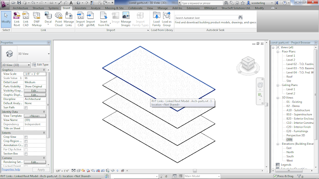

Once you select the floor it will take the floor item and
create a part which will allow us to divide into separate pours. This will allow us to use our tools in
Navisworks and also Revit to calculate the actual volume of concrete in the
floors. During this process it is a good
idea to make a duplicate view of the model view you’re working with. When parts are created it merely adds to the
project and does not do away with your particular item. In this view I hid the walls to view the
floors better.
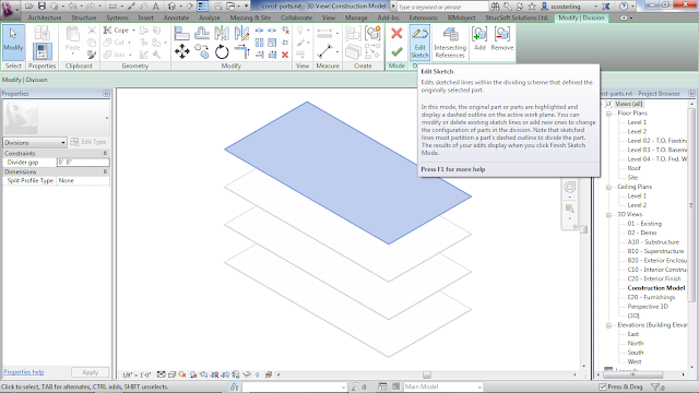
After making parts of all the floors we then need to divide
them into our separate items/pours.
Select one of the floors and locate the “Divide Parts” tool in the Parts
contextual tab.

Once you have selected the Divide parts icon you have
several option of creating the individual items. One is using the edit sketch tool to draw
lines on the parts. As long as you cross
the border of the outline it will use them to divide the part. You also have an option to use the Intersecting
References to make divisions when using your structural grid for example.

You’ll notice that I have chosen to use the Intersecting
References option to divide my part.
Here is the resulting image. For
saving time and steps I will only do this one slab and then I’ll show you how
it looks within Navisworks.


Once you have completed dividing your parts you will want to
export your Revit project out to Navisworks as a NWC file. For this example make sure you export only
the view you’re looking at. You’ll find
the export tool under the Applications Tab, The Revit “R”, now browse to the
NWC file type.

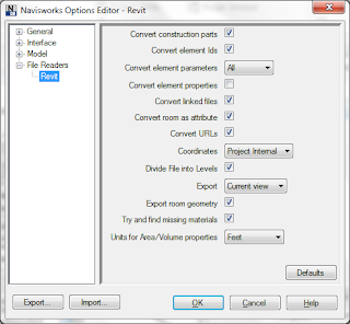
Once you select the NWC export option you’ll have a chance
to change the options if need be. Always
make sure the “Convert construction parts” is selected. If you don’t want the linked file in the
Navis file deselect the “Convert linked file” button.

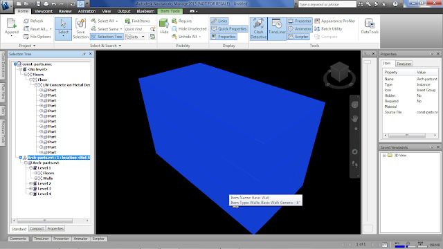
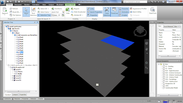
Once you open Navisworks you will append your construction
file that you exported out to the NWC and see that the linked file comes in
with the parts that you created. Let’s
select the linked Revit file and Hide it.
This will let the parts show up that we created within Revit.
So we have the link in, the parts are looking good and now
we get to work our magic on the file and link our project schedule to the
parts. As you can see this new workflow
is needed when we want to schedule our model to our Microsoft Project or
Primavera software.
The problem with this workflow is that if you want the
linked file to come in with the specific display changes, those changes do not
come across to Navisworks. There are
several possibilities we can work by.
- Not using Convert Links and creating a 3D View in the Linked RVT itself with the same overrides and exporting it.
- Not using Convert Links and binding the link temporarily before exporting to an NWC.
- Exporting with convert links with the extra elements and then using Find Items to create search sets based off of ORed conditions to find elements based off of their category. You can select the search set, to select those items and hide them. Hidden items are ignored when running clash tests.
We came across these when working with a situation that
needed this workflow.
Well, I hope that this little bit of information has helped
you in whatever situation you find yourself.
We at Sterling Systems can help you with your technical
issues and your business needs. Just
give us a call at (480) 719-4599 and we’ll be happy to assist you.
Steve Coburn, Applications Engineer
No comments:
Post a Comment