CloudWorx for Autodesk Revit
Step 1. Install CloudWorx for Revit 1.1
Step 2. Follow the normal process of installing the software to your hard drive. Revit will need to be closed down during the install.
Step 3. Once install is complete, open Revit.
Step 4. You will need to start with an Architectural template or office standard template if available.
Step 5. You now will have an additional tab at the top labeled CloudWorx. Click on CloudWorx tab > Project panel > Import MS View > Import MX View.


Note: The following steps are in reference to
installing the Leica Geosystems Cyclone 8.1.1 software package prior to opening
Revit. Due to your licensing you may not
have the ability to complete this function and future steps in this article.
Step 6. When
prompted to input CLM license server name click OK. Sometimes “Localhost” must be submitted in place
of leaving it blank.

Step 7. The
Import ModelSpace View dialog box
will pop up allowing you to browse to the project you wish to import. Select the [ . . . ] button allowing you to find the file.

Step 8. Navigate
to your “ModelSpace” view as before
in the Cyclone program.

Step 9. Open
up the “ModelSpace View 1”.

Step 10. You
should now see that view in the dialog box under Connection String.

Step 11. Click
OK.
Note: Depending on your CPU, ram and the file
size the process of bringing in the points may take a couple of minutes. Zoom
All (ZA) to view the entire point cloud.
Step 12. Depending
on a few factors of your display driver, Revit’s graphic display settings and
cyclones Open GL Mode setting the
points may not look correct. If
something seems to be off or all the points are a single color, among other
issues, we will need to go inspect the Open
GL Mode setting. If you are having a
difficult time moving around the cloud, changing these settings will also help.
Modifying the Open GL Mode
Step 13. Browse to the Start Menu > Leica Geosystems > Cyclone 8.1.1 > Utilities > OpenGL Modes.

Step 14. In the Supported OpenGL Modes dialog
box you will see the following screen.

Step 15.
You will need to look for any
mode that has the following settings available.
RGB 32
ZBuf 32
DblBuf Y
SW Y
HW n/a
OpenGL Y
Note: In order to see the difference between the
options you will need to close and restart Revit.

Step 17. Before you close out Revit you
will need to save the project in the CloudWorx Project pull down.

Step 18. Once this is all done and the
settings have been decided on you can then go to work on the project.
Step 19. The first thing we need to do for
setting up the project is to make sure that our levels are at the right
elevations. Open up an elevation view and review the locations of the cloud and the
level marks for level 1 and level 2. We
can change either the level’s elevation or move the point cloud to suit our
project template. If we move the point
cloud you will need to unpin it and make sure that you have your selection
methods all checked.


Step 20. Now that we have situated the
cloud you will want to view it in the 3D view.
Migrate to the side of the building you wish to see and then we can
start working the cloud to view a floor plan.
Step 21. Click CloudWorx tab > Clipping panel > View X drop-down > Z Axis.
Step 22. Single click at the #1 line,
under the ceiling. Then double click at
the #2 line and this will create a section cut for the floor plan.


Product of
“Z” slice.
Step 23. Rotate your view as to see the
top view and then rotate to have north at the top of the page.

Step 24. You now use your wall tool within
Revit to snap to the cloud and input the walls.
You may wish to rotate the building as to not have issues when drawing
walls off axis.
Step 25. If you decide to rotate the
building you will be able to use Autodesk Revit’s rotate option to do so, but
once you close out of the project the building will rotate back to its default
setting.
Note: In order to keep the
rotation we must go into the Cyclone software and change the UCS settings for
the project. If this is not available
then you will need to upgrade the software to include that option as this is
not available within the “Viewer”.
Step 26. Open Cyclone 8.1.1 to the project
file that you have loaded in to the Autodesk Revit project.
Note: I usually
always open the unified file.

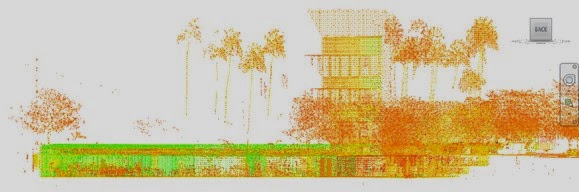
Default layout of project without any modification so far. Notice the location of the “Origin”.
Step 27. Our next step will be to select
three points in the cloud to use as reference points to change the UCS
rotation.
Note: Use
your mouse buttons to orient the view to the corner you would like to use for your
origin and rotation center. Select “View Mode”
and use your Left – Rotate, Right – Pan, Middle
(held down while moving up and down) –
zoom in and out.

 Pick Mode
 Multi-Pick Mode
 View Mode
 Seek
Seek
Step 28. Using the
above buttons try to zoom in to the corner so that you can differentiate the
surfaces of the corner so that you can pin point a good origin for your first
point. Using the “Multi-Pick
Mode” select the first point as shown above.

Step 29. As you go to pick multiple point
switch between the Multi-Pick
Mode and the View Mode to view
the following points.
Note: Remember
to always go back after rotating and moving to the Multi-Pick Mode or else
you will lose the previous points. If
you chose to use the Pick Mode, holding SHIFT+LEFT CLICK will select
multiple points as well.
As you can see I have
selected my first point. I try to get a
point that will be on the same surface as the Orange colored surface as I will
use this as my North facing wall.
Step 30. Select points number 2 and number
3, consecutively as shown below.

In order to pick point #2
you may have to rotate the view around as such.

Step 31. After you have selected the three
points desired click View
> Coordinate System > Set from Points.

Step 32. In the Set Coordinate System from Pick points dialog
box, review the options for changing the values of X, Y, Z and the angle for
the Azimuth Point. Since I want the
point #3 to be in the West direction I need to change it from 0 degrees to 270
degrees. This will orient the surface
that point #1 and #3 create as my North face.
I recommend leaving the X, Y, and Z coordinates at the default settings
until you feel more comfortable with making those modifications.

Step 33. Rotate your view to the “Top View” to see
the changes in effect.


Now that you have this modification made in the
Cyclone project it will then transfer to the Revit project the next time you
open it up. In order to keep the right orientation for your building these
steps must be completed otherwise you will lose the layout and have to rotate
your cloud every time.
We at Sterling Systems can help you with your
technical issues and your business needs. Just give us a call at (480) 719-4599
and we'll be happy to assist you.
Steve Coburn, Applications Engineer

No comments:
Post a Comment